HIFI Diary: A Detailed Primer on HIFI Cables – The Power Cord Edition
Foreword
For a very long time, the HIFI community has fiercely debated the role of cables; the argument between cables making a difference and being useless has raged for decades without a clear winner. During my own reviewing process, I have, more than once, wrestled with this very question. Yet, in the vast majority of cases, I firmly recognize that cables can alter a system’s timbre and enhance its overall performance. In the following, I will attempt to explain the secrets of HIFI cables in the most accessible way possible, offering a genuinely meaningful popular science introduction. This article is very long and may feel somewhat dry, but I believe it is a piece truly worth reading for any serious audiophile.
Please note that this primer is intended solely as an introduction to the knowledge; any brand or model mentioned in the text serves only as an illustrative reference and does not constitute a recommendation. Given the limits of my knowledge, it is almost certain that this text contains errors, and I welcome corrections from experienced enthusiasts. Furthermore, I have long been writing HIFI explainers. Reading this primer will be most beneficial if you have at least some understanding of system clocking. Additionally, I have analyzed some cable topics years ago in the following articles:
HIFI Diary: Starting from SATA Data Cables, Discussing the Chaos of DIY Cables – RainLain
HIFI Diary: Selection and Discussion of Ethernet Cables – RainLain
HIFI Diary: A Comparison of Solders – RainLain
HIFI Diary: How USB Cables Affect Sound Quality – RainLain
Main Body
To understand the power cord, we need to pull it down from the altar of “mysticism” and place it squarely into the science of electrical engineering and signal processing. In reality, many misunderstandings about whether power cords make a difference stem from viewing them as isolated components, rather than as the physical interface between “the device’s internal power supply unit and the chaotic energy environment of the external power grid.” In this final meter of power delivery, the influence a power cord exerts on different types of equipment follows two distinctly different physical laws: for low-power front-end devices, it is an antenna that determines the noise floor; for high-power back-end devices, it is the internal resistance that decides the life or death of dynamic performance.
1. Low-Power Front-End Devices
Let us first dissect the impact on low-power front-end devices. This category encompasses digital interfaces, digital-to-analog converters (DACs), clocks, phono stages, and even the majority of operating states of preamplifiers. The common characteristic of these devices is that their internal circuits process very weak voltage signals or extremely precise timing signals. Their own power consumption typically ranges from a few watts to tens of watts, and their current demand remains stable in the milliampere range. Intuitively, a DAC chip requiring only a few hundred milliamps of current seems to place no demand on the current-carrying capacity of the power cord. However, at this level, the power cord plays the role of a passive antenna picking up electromagnetic pollution, as well as a conductive path that injects grid noise into the heart of the device without attenuation.
Physically speaking, any segment of metal conductor that lacks ideal shielding at both ends acts as an antenna in free space. Your power cord, along its roughly 1.5 to 2-meter journey from the wall outlet to the component’s IEC inlet, is completely exposed to a complex high-frequency electromagnetic field composed of 2.4GHz or 5GHz Wi-Fi, 4G/5G cellular signals, Bluetooth, and even nearby radio broadcast stations. This ubiquitous RF interference will induce tiny high-frequency currents on the live, neutral, and ground wires of the power cord through electromagnetic induction (a phenomenon demonstrated by Hertz’s experiments).
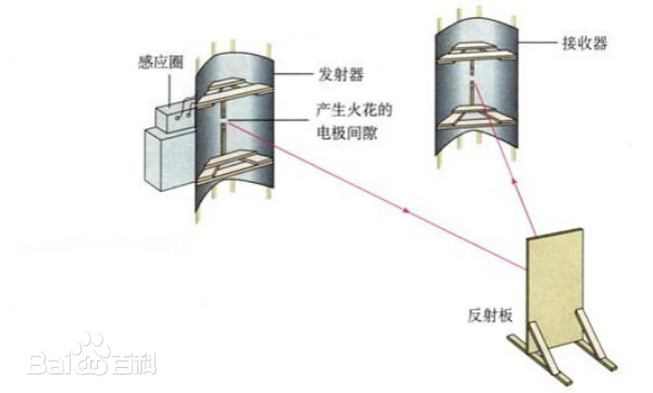
Due to their simple construction, ordinary power cords lack an effective shielding layer or filtering structure. These induced high-frequency noises charge straight into the component’s power inlet in the form of common-mode interference (in-phase noise on the live and neutral lines relative to ground) and differential-mode interference (out-of-phase noise between the live and neutral lines). Once inside the chassis, they seek out every possible path to couple into sensitive analog or digital circuits.
Thus, we arrive at the first core requirement for a HIFI power cord: shielding.
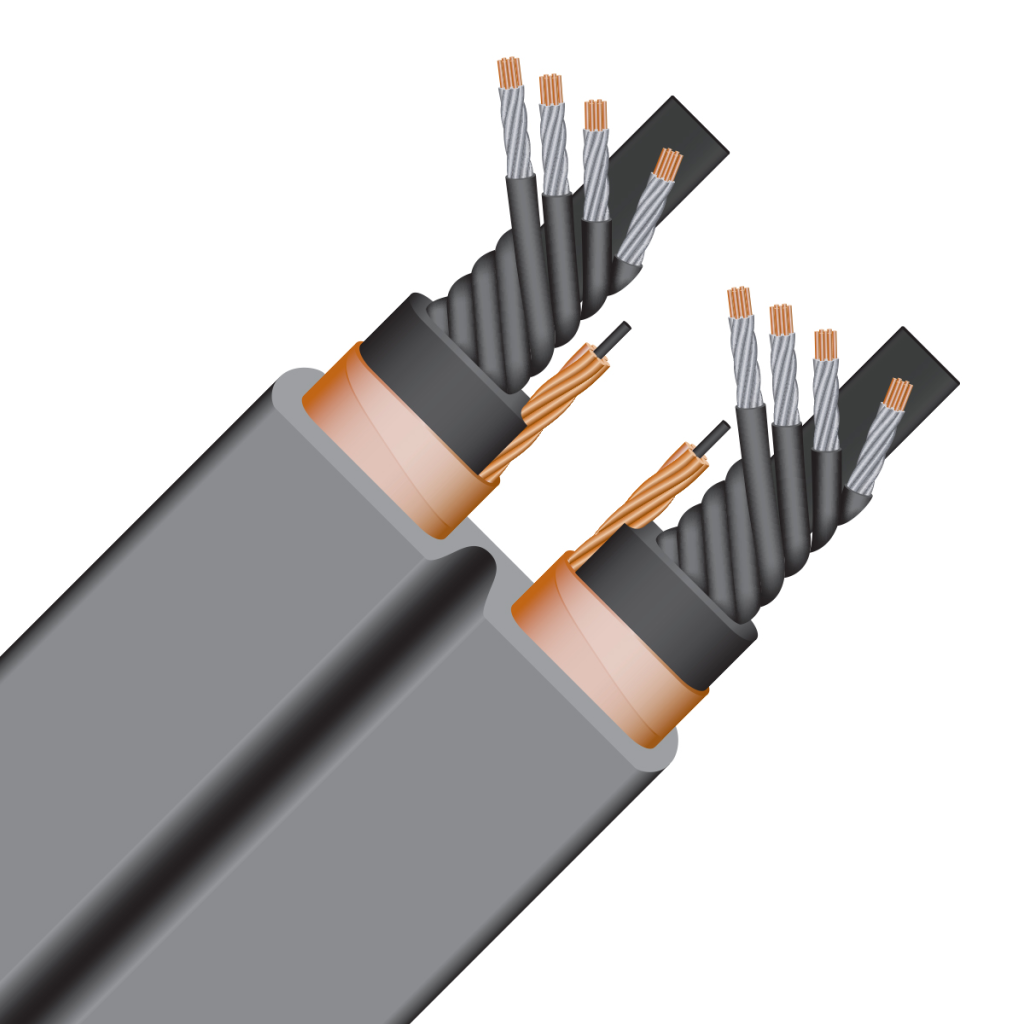
The scientific basis for a high-quality audiophile power cord lies in its typically dense braided copper shielding mesh, combined with an aluminum foil striving for 100% coverage. This creates a physical barrier against radiated interference. Going a step further, some cords incorporate a cylindrical ferrite core near the component end, or integrate a specially structured filter network within the cable body. This filter network leverages the inductor’s property of “passing low frequencies and blocking high frequencies,” allowing the 50/60Hz mains current to flow unhindered while presenting an extremely high impedance to high-frequency RF noise, effectively blocking it. This combined action of physical shielding and electronic filtering does not alter the music signal; it merely clears away background noise that shouldn’t exist and would otherwise mask subtle musical details and micro-dynamics.
Key Point: The Difference in Shielding Quality
[展开/折叠]-
In our common understanding, shielding a power cable simply means “wrapping the wire in a copper mesh.” However, shielding is actually an extremely precise engineering discipline—different designs can yield a performance difference of more than 1,000 times.
1. Shielding Structure: Ordinary Cables’ “Single Layer” vs. HiFi Cables’ “Multi-Layer Fortification”
Most ordinary power cables use the lowest‑cost, simplest single‑layer braided copper mesh shielding, with coverage typically between 70% and 95%. This type of shielding has some effect against low‑frequency electromagnetic interference, but it is ineffective against the ubiquitous high‑frequency radio‑frequency interference (RFI). For devices that process delicate high‑frequency signals—such as DACs and streamers—this level of protection falls far short.
HiFi power cables generally employ a multi‑layer composite shielding structure. The core improvement is adding a 100% coverage aluminum foil layer inside the traditional copper mesh, forming the classic “aluminum foil + copper mesh” combination. This aluminum foil plays a crucial role: it fills the gaps in the braided copper mesh and fully reflects and blocks high‑frequency interference. For example, Neotech power cables often use a copper foil + copper braid structure, while some Oyaide power cables spare no expense in using copper foil as the shielding layer, pursuing maximum shielding effectiveness. This reflects an uncompromising pursuit of “pure power delivery.”
2. Shielding Material: The Starting Point of Auditory Tuning
Beyond the basic structure, HiFi cables also pay great attention to the shielding material itself, treating it as a form of fine auditory tuning. Ordinary power cables typically use low‑cost industrial copper or aluminum‑magnesium wire. In contrast, HiFi cables use the same high‑purity oxygen‑free copper (OFC) or even single‑crystal copper as the main conductor to make the shielding mesh, reducing electromagnetic energy loss in the shield. Going a step further, Furutech, on its flagship Project V1 power cable, uses its patented “α‑copper foil” and “α‑copper braid” treated with special cryogenic and demagnetizing processes—aiming not just for shielding efficiency but also for material purity.
3. Shielding Craftsmanship: From “Coverage” to “Technique”
In HiFi power cables, shielding is not merely a stack of materials and layers—it also represents technological breakthroughs:
Active Shielding: Some HiFi power cables have introduced active shielding technology. For instance, Titan Audio from the UK uses an external active shielding module to generate a stronger shielding field around the cable, further blocking interference.
Precision Stranding and Direction: The braiding pitch of the shielding mesh, the thickness of each strand, and other factors all affect shielding performance. HiFi cables precisely control these parameters. Even the winding direction of the shield is carefully controlled to cancel electromagnetic effects caused by mechanical vibration.
Special Shielding Solutions: Some HiFi cables explore alternative approaches, using special liquids, Ferox, or other new materials to simultaneously achieve shielding, vibration damping, or specific tonal tuning.
When high-frequency noise evades the interception of physical shielding and filtering and invades the interior of the device, its primary target is the key components that power precision chips, such as Low-Dropout Regulators (LDOs). Whether providing a 3.3V or 1.2V operating voltage for a DAC chip, or supplying a constant, pure voltage for a femtosecond clock oscillator, performance is highly dependent on the LDO. However, all LDOs possess a fatal weakness: their ability to reject power supply ripple at the input drops sharply as frequency increases. A typical LDO can easily achieve over 60dB of Power Supply Rejection Ratio (PSRR) for 100Hz mains ripple, meaning it can attenuate input fluctuations by a factor of 1,000 before output. But when the frequency rises to 1MHz, the PSRR may plummet to around 20dB, providing only a factor of 10 attenuation. Above 10MHz, the internal feedback loop gain of the LDO has decayed so much that it virtually loses all suppression capability. Input noise can penetrate to the output almost unattenuated, directly superimposed onto the power supply rail of the chip.
High-frequency RF noise is fatal to the clocking systems of digital circuits. A clock crystal oscillator is a device that converts DC power energy into a precise, periodic vibration signal. If microscopic broadband noise is superimposed on its power supply rail, this noise directly modulates the oscillator’s output, manifesting as increased clock “phase noise.” In the time domain, this is the well-known jitter, where the edges of the digital signal’s square wave deviate from their ideal positions. Jitter does not cause data errors; a “0” will still be recognized as a “0.” However, during Digital-to-Analog Conversion (DAC), this unstable clock causes the timing points at which the analog waveform is reconstructed to tremble, directly degrading into a blurred soundstage, drifting image focus, and a deterioration of instrumental harmonic texture. It can be said that, by injecting noise into the clock system, the power cord indirectly becomes a decisive checkpoint for sonic finesse. For analog circuits like phono stages or preamplifiers, their amplification factors are extremely high, typically reaching 40 to 60dB, representing a voltage amplification of 100 to 1,000 times the input signal. Any minute noise on the power rail is also amplified synchronously at the output, directly becoming audible background hiss or interference.
Key Point: Clock Crystal / Oscillator
[展开/折叠]-
In any digital audio device, a “metronome” is needed to unify the working rhythm. That metronome is the clock crystal oscillator. Its core principle is the piezoelectric effect of a quartz crystal – when voltage is applied, the crystal generates extremely stable mechanical vibrations, and these vibrations in turn control the switching rhythm of the circuit, outputting a series of square‑wave pulses with fixed time intervals.
In an ideal world, the pulses of this clock signal would repeat with absolute periodicity, and the arrival time of each rising edge (the moment the square wave jumps from 0 to 1) would be perfectly accurate. In reality, no crystal is perfect. The frequency stability of a basic‑grade crystal (e.g., a Temperature‑Compensated Crystal Oscillator, TCXO) is on the order of parts per million (ppm). In contrast, an audiophile‑grade femtosecond crystal, such as the Crystek CCHD‑957 or the Accusilicon AS318 series, can achieve frequency stability on the order of parts per billion (ppb) – with prices ranging from a few yuan to over a thousand yuan. For 44.1kHz sampled audio, if the clock deviates by even one nanosecond within one second, it corresponds to an error in the least significant bit of 16‑bit audio.
Key Point: Phase Noise
[展开/折叠]-
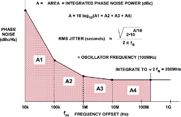
With a clock oscillator in place, the core metric for evaluating its output quality is phase noise. Phase noise is the frequency‑domain description of short‑term frequency instability. It captures which frequency range the noise occupies. A perfect sine wave (or the fundamental of a square wave) would appear as a single vertical line in the spectrum – all energy concentrated exactly at that frequency. In reality, thermal noise inside the crystal, impurities and defects in the crystal itself, and tiny voltage ripples on the power supply rail all modulate the clock signal, causing its output not to be a single point but to spread symmetrically on both sides of the center frequency, forming a broadened spectral skirt – like a sharp tower becoming blurred and wide at its base.
Audio engineers typically measure phase noise as the noise power ratio at a specific offset from the carrier frequency. For example, an excellent femtosecond oscillator may have a phase noise as low as ‑160 dBc/Hz at a 1kHz offset. This means that at 1kHz away from the main clock frequency, the noise energy per 1Hz bandwidth is 160 decibels below the central carrier power – more than one quadrillion times lower. Lower phase noise means a “purer” clock.
Key Point: Jitter (Timing Error)
[展开/折叠]-
Phase noise is observed in the frequency domain, but its consequences manifest in the time domain as jitter (timing error). Jitter can be seen as the direct projection of phase noise onto the time axis. If phase noise causes the clock frequency to “drift” within a small range, then when the rising edge of the clock arrives, its arrival time deviates from the ideal position. This deviation – being “early” or “late” – is jitter.
In digital‑to‑analog conversion, jitter is fatal. The D/A converter chip updates its output voltage on each rising edge of every clock cycle. According to classical quantization theory, when there is timing jitter with an RMS value of δt at the sampling moment, the resulting SNR degradation can be expressed as: SNR = –20 log₁₀(2πf δt). Taking a 1kHz sine wave as an example: if the DAC’s clock has an RMS jitter of 100 picoseconds (ps), the SNR is limited to approximately 68dB – equivalent to the theoretical limit of 12‑bit audio. This means that a 24‑bit master file essentially loses its high‑resolution significance. For every tenfold worsening of jitter, the SNR loses 20dB. That is why, even if the digital data is error‑free, jitter can cause audible effects such as collapsed soundstage, blurred imaging, cloudy detail, and harsh highs – it directly damages the accuracy of the reconstructed analog waveform.
2. High-Power Amplification Devices
Now, let us turn our perspective to the other extreme: high-power back-end devices, represented by power amplifiers. The power cord connected here is no longer an antenna, but a high-demand impedance element connected in series within the main circuit loop. The challenge it faces switches from noise suppression to energy transmission.
A transistor power amplifier driving large loudspeakers, when amplifying music signals, does not draw AC power directly from the wall outlet. Instead, it rapidly pulls DC current from a large reservoir capacitor bank inside the chassis. When a sudden, large dynamic transient arrives in the music — say, a cannon shot or a forceful kick drum — the amplifier’s output stage needs to instantaneously deliver peak currents of tens of amperes to the speaker. Assume an amplifier needs to output 200 watts instantaneously into an 8-ohm load; according to the formula P=I²R, the current flowing through the speaker cable at that moment is √(200/8) = 5 amperes. However, considering that speaker impedance can dip to 2 ohms, along with factors like saturation voltage drop in the amplifier’s output transistors, the instantaneous current demand on the power supply section can easily exceed 15 amperes or even higher. This huge current demand is first met by the filtering capacitors within the amplifier. The discharge of the capacitors causes a momentary voltage drop across their terminals. At the moment of this voltage dip, the diodes in the full-wave rectifier bridge conduct, rectifying the AC from the transformer’s secondary into pulsed DC to replenish the capacitors. Simultaneously, through electromagnetic induction, the transformer draws a surge of instantaneous current from the wall outlet via the power cord.
Key Point: Transduction Formulas
[展开/折叠]-
Determine the peak load power:
(If the crest factor is 12dB, that corresponds to a voltage ratio of 4x and a power ratio of 16x.)Derive the current drawn from the power supply:
Calculate the instantaneous voltage drop across the capacitor:
Calculate the voltage drop along the cable:
And here, we officially introduce the second core metric determining a power cord’s superiority or inferiority: resistance and inductance.
Resistance causes a direct voltage drop. Under a peak current of 15 amperes, even if the total loop resistance of the cord (the sum of the resistance of the live and neutral return paths) is a mere 0.1 ohm, it will produce a voltage loss of 1.5 volts, directly reducing the effective voltage received by the transformer’s primary and causing a “soft-footed” effect within the power supply. However, the obstruction posed by inductance is more critical and insidious. In the scenario where the amplifier demands instantaneous dynamic current, the rate of change of current (di/dt) is extremely high. Inductance possesses the physical property of resisting changes in current, generating a counter-electromotive force. A poorly constructed power cord, with its relatively large parasitic series inductance, acts as if an element that impedes rapid change has been placed in series with the energy supply path. When the amplifier’s power supply attempts to instantaneously draw a large current from the wall outlet to replenish the capacitor voltage, it is obstructed by the cord’s own inductive reactance, causing a lag in current delivery. The capacitor voltage cannot be replenished in time and experiences a momentary sag. In macro-level listening perception, this is the direct physical mechanism behind dynamic compression, weakened low-frequency control, and a collapse in soundstage scale. Particularly for traditional high-power amplifiers employing unregulated power supply designs, where the internal supply voltage fluctuates directly with the mains grid, the low-impedance characteristic of the power cord becomes even more critical.
Key Point: Determinants of Resistance
[展开/折叠]-
The physical essence of resistance is the hindrance caused when free electrons collide with lattice atoms while drifting through a conductor. From an engineering standpoint, the DC resistance of a uniform conductor is given by the simple formula:
where is the electrical resistivity of the conductor, is the length, and is the cross‑sectional area.
Material sets the starting point for . At 20°C, the resistivity of pure copper is approximately ; that of pure silver is about – silver is about 8% lower than copper. Brass, due to alloying, can have a resistivity as high as – 3.7 times that of pure copper. This is the physical reason why ordinary power plug contacts made of brass degrade sound quality. Purity further fine‑tunes : moving from 4N copper to 6N copper reduces resistivity by a few percent (by reducing heteroatoms that scatter electrons in the lattice).
Cross‑sectional area is the most direct engineering lever. The IEC standard requires a minimum cross‑section of only for power cords of typical desktop equipment. By contrast, typical HiFi power cables use conductors of or even – five to eight times larger. A larger cross‑section not only lowers DC resistance but is even more critical for the AC resistance discussed later.
Another easily overlooked factor is contact resistance at the plugs. A high‑quality IEC connector has a contact resistance below 1 mΩ per contact point. However, ordinary brass plugs, due to surface oxidation and low contact pressure, often exceed 10 mΩ. Each contact point is in series with the circuit, and the cumulative effect of several such points is equivalent to adding meters of cable length. This is why high‑end power cables care so much about plug materials – copper base plated with gold or rhodium – the fundamental goal is to lower contact resistance.
Key Point: Determinants of Inductance
[展开/折叠]-
For a power cable, inductance mainly comes from self‑inductance as a parasitic parameter. A single round straight wire has an inductance of about –. However, a power cable forms a loop with two parallel conductors – live and neutral. The loop area between the two conductors directly determines the total inductance. When the live and neutral wires are tightly twisted together, the loop area is minimized and the inductance is very low; when they are loosely separated, the loop area is large and the inductance increases significantly. This is the fundamental physical mechanism behind why twisted‑pair structures reduce inductive reactance.
The AC characteristics of a power cable also introduce frequency‑dependent resistance: due to the skin effect, high‑frequency currents are pushed to the conductor surface, reducing the effective conducting cross‑section and making the high‑frequency AC resistance greater than the DC resistance. Multi‑strand fine wires (Litz structure), each strand insulated from the others, provide an individual surface layer for high‑frequency current, effectively suppressing the rise in resistance caused by the skin effect. In other words, the power cable actually presents a frequency‑dependent complex impedance , rather than a simple DC resistance.
Translating these factors back to the macro sonic impression: a power cable with low resistance and low inductance ensures an extremely low and stable output impedance. This allows the amplifier’s power supply to keep up with instantaneous dynamic demands – without lag or compression – thereby supporting the full‑bandwidth dynamic and soundstage framework.
Thus, the complete role of the power cord in the system is revealed. It is not an isolated tuning accessory, but a physical extension of each device’s power supply design. For the front end, it is a barrier that isolates interference and reduces the noise floor. For the back end, it is a conduit that lowers dynamic internal resistance and guarantees instantaneous energy delivery. This dual demand for low noise and low impedance naturally draws our gaze toward the material foundation that achieves these physical properties — the conductor material constituting the cable body itself. The differences in the microscopic grain boundary structure of copper and silver of varying purity directly determine the scattering and losses suffered by charges as they travel through the conductor. These performance differences are then transcribed into the perceptible sonic signature within the audio system.


You May Also Like

HIFI Diary: How to Write a Good Review? How Are Hi-Fi Reviews Actually Done?
Classical Diary: The Last Glory of Roman Orthodoxy — Giovanni Pierluigi da Palestrina (Part 7)